
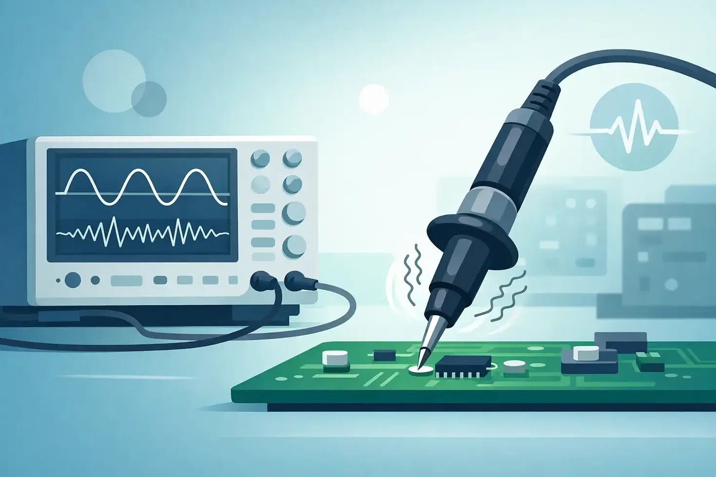
How to Reduce Probe Vibration in Test Setups
- russellgarrigan
- Aug 13
- 6 min read

A probe tip can appear stable under an inspection microscope and still move enough to corrupt a low-current sweep, intermittently open an RF contact, or damage a fragile pad. Learning how to reduce probe vibration starts with treating the probe station as a connected mechanical system, not as a collection of independent components. The floor, isolation platform, station frame, chuck, microscope, manipulators, cables, and environmental hardware can all contribute motion at the device under test.
For semiconductor characterization, the acceptable vibration level depends on the measurement. A high-voltage power device test may tolerate movement that would make sub-micron probing impossible. Low-noise DC, RF/mmWave, photonics, cryogenic, and wafer-level reliability work often expose vibration problems quickly because contact stability and signal integrity are tightly linked. The practical objective is not simply to make the station feel rigid. It is to identify the frequency, path, and magnitude of motion that affects measurement repeatability.
How to Reduce Probe Vibration at the Source
The most cost-effective fix is usually controlling the vibration source before adding more isolation hardware. Start by observing when the issue occurs. Does probe movement increase when personnel walk nearby, when an HVAC unit cycles, when a vacuum pump starts, or when a thermal system begins regulating? A repeatable trigger is valuable diagnostic information.
Floor-borne vibration is common in shared labs, cleanrooms, and production areas. Foot traffic, forklifts, adjacent equipment, building mechanical systems, and elevators can transmit low-frequency energy through the floor into the station base. A manual probe station positioned near a high-traffic aisle may show more instability than the same station moved only a few feet to a structural slab or lower-traffic location.
Airborne and locally generated vibration also matter. Fans in a light-tight enclosure, compressed-air lines, vacuum hoses, chiller pumps, and nearby acoustic sources can excite station components. In sensitive optical or low-current work, avoid directing airflow across probe arms, cables, or open enclosures. If a pump or chiller is necessary, place it on a separate support where practical and use appropriately rated flexible connections to prevent the hose from becoming a vibration bridge.
Before purchasing equipment, check simple mechanical conditions. Confirm that the station base is level, mounting hardware is secure, and all feet or isolator mounts are carrying load evenly. A frame that rocks slightly can amplify vibration dramatically at the probe tip. Loose panels, improperly seated microscope components, and unsecured cable trays are equally capable of creating intermittent problems that look electrical rather than mechanical.
Build Isolation Around the Actual Test Requirement
Vibration isolation platforms are often the right solution, but their selection should follow the application rather than a generic preference for the softest or most elaborate system. An isolation platform must support the complete operating mass of the station, accessories, and expected tooling while controlling the frequencies that matter to the measurement.
Passive pneumatic isolators are widely used for probe stations because they can provide effective attenuation above their natural frequency. They require proper leveling and loading. If the station's center of mass is poorly distributed, or if a heavy microscope, shield enclosure, thermal assembly, or optical positioner is added later, isolation performance can degrade. Recheck level and isolator settings after any major configuration change.
Active isolation can be appropriate where low-frequency floor vibration is severe or where the test requires exceptional stability. It is not automatically better for every lab. Active systems add cost, power requirements, system complexity, and sometimes service considerations. For a general-purpose manual probing environment, a properly sized passive platform combined with sound station setup may deliver the required performance at a more practical budget.
Isolation should not be confused with structural stiffness. A probe station still needs a rigid, well-damped frame, stable manipulator mounts, and a controlled work surface. A soft isolation platform underneath a flexible table can create a slow, noticeable sway rather than a stable test environment. The base, table, and station should be evaluated as one stack.
Avoid bypassing the isolators
An isolation system only works when unwanted mechanical paths do not bypass it. A rigid conduit, tightly tensioned cable bundle, compressed-air line, or vacuum hose connected between the isolated station and a fixed wall or floor can transmit vibration directly into the system.
Route cables with enough slack to accommodate small station movement. Support heavy cable bundles independently rather than hanging their full weight from a probe arm, instrument port, or microscope assembly. For high-frequency test, this needs careful engineering: RF cables should have controlled bend radii and strain relief, but should not be pulled tight across the isolation boundary. The same principle applies to triax, coax, fiber-optic, cryogenic, and high-voltage cabling.
Stabilize the Probe Station and Manipulators
At the point of contact, manipulator stiffness and probe geometry often determine whether residual vibration becomes a measurement problem. Long, extended probe arms have lower stiffness and can resonate more readily than compact configurations. Whenever access permits, minimize unnecessary extension and use a probe holder suited to the required probe type and force.
Probe overtravel deserves particular attention. Excessive overtravel increases contact force and may reduce visible bouncing in some cases, but it can damage pads, deform delicate structures, increase scrubbing, and create a false sense of stability. Too little overtravel leaves the contact vulnerable to small disturbances. The right setting depends on pad metallurgy, probe style, temperature, and test current, so it should be established through repeatable contact verification rather than visual judgment alone.
The device fixture or wafer chuck must also be rigid. A wafer that is not held flat, a die mounted on uneven adhesive, or a custom substrate mount with insufficient support can shift under probe force. This is particularly relevant for decapsulated parts, power devices, thin wafers, and irregular substrates. A custom mount may be more effective than additional isolation when the real issue is local device support.
Thermal testing introduces another trade-off. Heated chucks, cryogenic stages, and liquid or gas cooling connections can add both mass and mechanical disturbance. Flexible lines should be routed carefully, and thermal control hardware should be allowed to settle before critical measurements. Fast temperature transitions may create temporary movement through material expansion, fluid flow, or controller activity. If repeatability changes only during thermal regulation, the remedy may be a revised test sequence rather than a different probe station.
Verify Vibration With Measurement Data
A microscope image is useful for gross motion, but it is not enough to characterize a difficult vibration problem. Start with a controlled baseline: record contact resistance, leakage current, noise floor, or a known DC/RF response while the station is quiet. Then repeat the measurement while introducing suspected disturbances one at a time, such as walking nearby, operating a pump, cycling the enclosure fan, or moving a cable.
For advanced diagnosis, use an accelerometer or vibration sensor at several locations: the floor near the station, the isolation platform, the station base, and a representative point near the manipulator mounting area. Comparing these locations helps distinguish floor excitation from frame resonance or a local accessory problem. Frequency information is especially useful because it can reveal whether the system is responding to building vibration, rotating equipment, or a natural mode in an arm or fixture.
Electrical indicators should be part of the verification process. Watch for changes in probe contact resistance, intermittent continuity, current noise, capacitance drift, or scattering-parameter instability. In photonics testing, monitor optical coupling stability alongside mechanical movement. A system can have low visible displacement but still produce unacceptable results if probe force or fiber alignment is changing at the device interface.
When a System-Level Review Is Worthwhile
Persistent vibration is rarely solved by replacing one component without reviewing the whole test environment. A probe station may have excellent manipulators but sit on an undersized platform. An effective isolation platform may be defeated by cable routing. A stable station can still produce inconsistent data because the DUT mount flexes during probing.
Micron Probing can help configure complete probing environments that account for station architecture, vibration isolation, enclosures, thermal accessories, custom substrate mounts, and instrument cabling together. That approach is useful when a test setup must support several applications, such as DC characterization, RF probing, high-voltage testing, or temperature-dependent analysis, without compromising the most sensitive measurement.
The final test is straightforward: after each change, repeat the measurement that originally exposed the problem. Stable probe contact should show up not only as a quieter microscope view, but as cleaner data, fewer retests, and greater confidence that the device behavior belongs to the device rather than the test setup.


Comments